
Introduction
In this article I'll touch on the Internet Of Things (IOT) and what it is. I will talk about, and show similarities and differences between a smart home versus an automated home. I will talk about different home automation software packages and different ways to gear your IOT devices towards making your home more of a smart home.
Internet Of Things
You may have heard the terms IOT or IOE before and said, what the heck is that. IOT stands for the Internet Of Things. Similarily, IOE stands for the Internet Of Everything. IOT and IOE, in it's broadest sense is the process of making the things that we use every day, in some way shape or form, connected to the internet. These things have various sensors and control functions. Being connected to the internet allows outside access to to the data and control that those sensors and controls provide. IOT is a way of simplifying the world around you. IDC, a market intelligence research firm, says that there are around 13 billion connected devices in use worldwide already. Business Insider (BI) Intelligence projects 34 billion devices will be connected by 2020.
Home automation projects
 One aspect of IOT that is becoming more common is home automation. Home automation is nothing new though. My start into home automation began many years ago with X10. I found it nice to be able to control devices remotely. With their software called ActiveHome, I could also automate things with motion sensors and timers using a computer. After using it for a bit, I found that there were things that I wanted to do that my X10 hardware could not. Since then I have tried a number of different software packages, most of which fit in the realm of home automation platforms.
 Some of these have included MisterHouse, Domoticz and most recently my VeraPlus controller. I have another blog post talking about my home automation setup. https://dan.bemowski.info/2017/06/11/my-home-automation-setup/
 One project I was a part of that geared itself toward being more of a smart home system than an automated home system. That project was called Open Source Automation, or OSA. The features that drew me toward the system were it's ability to integrate a number of different types of hardware into one system. Another thing that drew me toward it was it's focus towards being a smart home controller. When I was on the project, the smart home features were in their infancy, but moving forward.
Smart home vs automated home
So what is the difference between an automated house and a smart house. The ability for you to turn devices on and off from your phone, and scheduling lights and other devices to turn on and off on different schedules, simply means that you have an automated home. You may ask then, how is that different from a smart home. A smart home adds other layers on to the automated home system giving it a new level of functionality.
The broadest aspect of a smart home is gathering lots of data. Smart homes are made of many data gathering tools and sensors. Gather more data and you can make more intelligent decisions based on that data. Another thing we'll throw into the mix is objects. These objects have many properties. The properties of these objects, combined with data that your system has collected can now make smart decisions. Now your system is gearing up to be a smart house.
One of the biggest pieces of data in all of this, and the most difficult to manage, is occupancy sensing. A basic level of occupancy sensing is to put motion sensors in a room that will turn lights on and off. However, the use of a motion sensor will only tell your system that one or more people occupy an area. Now what if you could tell how many people were in that area. To take that a step further, what if you could tell exactly who was in a particular area. Now you can make smart decisions based on that added data.
People objects
 Previously we mentioned objects and their corresponding properties. So lets say we defined a person as one of those objects. We'll define two "person" objects using myself (Dan) and my wife (Karen) as examples. So let's say Dan likes the temperature in a room to be 70° and he likes a lot of light in a room. Two properties for Dan would then be "temp = 70°" and "lightLevel = 100%". Now Karen likes the temperature in a room to be 67° and have the lights a little dimmer, so her two properties would be "temp = 67°" and "lightLevel = 70%". Let's combine this with motion sensing with person recognition. You can now define your rule on your main controller to say:
If ( motion_sensed ) {
if (furnace_mode == off ) {
set furnace = on; //Turn the furnace on if someone is in the area
}
set furnace_temp = temp; //Set the temperature to the users desired temp
set lights = lightLevel ; //Set the lights to the users desired light level
}
}
So with that, if I walk into the room and the furnace is off, it will set the temperature to 70° and turn the lights on to 100%. If my wife walks in under the same scenario, The furnace will set itself to 67° and the lights will dim to 70%.
As you can see, the more data you can gather, the smarter, more informed decisions your automation controller can make based on that data. Using this approach can save energy and improve the quality of life for the occupants. You should now be able to tell the difference between a smart house and an automated house.
Conclusion
So to sum it up, an automated house gives you control of devices from an external source such as a smart phone and limited action from other sensors such as motion sensors. A smart house makes it's decisions using multiple factors and sensors. Check out the ongoing discussion on this topic on the MySensors website https://forum.mysensors.org/topic/7814/a-smart-home-vs-an-automated-home/ .
Related Images:


 I turned to OpenSCAD and came up with a basic design. The box was vented, it had mounting tabs for the PCB and a place to hold the battery box.
  I decided to make it easy to remove from the wall if needed and made the wall plate with two tabs that the cover could lock on to.
 This is the first prototype design of the 3D printed parts. Some minor changes have been made since this design. The first was to invert the center mount sections so the screws screwed in from the bottom. This put the wind direction vane on the piece with the square mounting peg and the anemometer was moved to the other piece. The reason for this was to keep rain from collecting in the small screw recesses and potentially getting inside the case. The next change which I am in the process of printing as I write this, is a new piece with a round mounting peg instead of a square one. This was done because of a later decision to mount everything using schedule 40 PVC electrical conduit.
 I had built some custom in-wall automation scene controllers based on
  All three of the circuit boards were built on standard 30mm x 70mm prototyping circuit boards like these. My first fully assembled version of the controller can be seen below. Though the design seemed to work good, they were a bit of a pain to put together.
  Building one controller on prototyping boards and wiring it all up took 4 hours or more. After building 3 of them and seeing how they worked, I wanted more, but I didn't want to spend all the time making them. So, it was time to get my feet wet on PCB manufacturing.
 For the design of the main board I broke out all digital and analog IO lines from the pro mini except for A6 and A7. I also have ground, raw 5 volt power plus the 3.3 volt regulated power from the pro mini available on 2 single inline header connectors. A4 and A5 on J3 also provide I2C capabilities to the front board. With all of these, the only limit to what can go on the front board is what you can fit in the small space..
 The design of the keypad board may look a bit crowded, but it was designed that way to make it flexible. Many different keypad designs can be made from this one board. I had gotten the idea for this type of design from a video I had seen by a guy in Australia named

 The buttons can have any text embossed on them, or they can just be left blank. Here are just 3 examples of the many different wall switch designs that can be made using this board. No need to have separate boards printed when you want to put together a new switch. Just grab a board, print the switch layout on your favorite 3D printer and screw it together. Done!
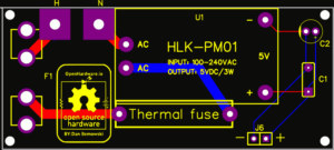 There is nothing fancy with the power supply board. It is based on the standard