
Description
This post is to describe how I used Sonoff modules with my Vera Plus automation controller. I'll explain the configuration and setup of the Sonoff, as well as the modifications needed to an existing plugin to make the whole setup work.
Details
 Sonoff modules are cheap Wi-fi controllable relay modules that are based off of the ESP8266 chip. Here I will describe how to control these with a vera home controller. The procedures described here should work for nearly any ESP8266 based relay module and are not exclusive to the Sonoff modules.
The basic outline of the procedures are as follows:
- Flash new firmware to the Sonoff or other ESP8266
- Set up and configuration
- Testing the device
- Installing the necessary plugin on your Vera
- The configuration settings
- Adding local control using the button
- Updating your Vera device based on the local button press
DISCLAIMER: I take NO responsibility for issues or problems that may arise from using the procedures outlined here. I am merely giving the information on what worked for me on the devices that I have. The procedures may be different for other ESP8266 modules. Please consult documentation on the modules that you have for more information. It should also be noted that this will wipe out the existing firmware on the device and it will no longer be able to be used as originally sold.
Flashing firmware to the Sonoff or other ESP8266
The first step in this process is to make sure we have the correct firmware loaded on your device. The firmware that we will be using for this project is the ESPEasy firmware which is an open source firmware for ESP8266 modules. There are a few ways to flash the firmware to the device, but the procedures I will outline here for flashing this firmware to the device involve the use of the Arduino IDE. One thing you will need to do the programming is an FTDI USB to serial adapter. These can be purchased on ebay cheap. Lets get started.
The first thing you will need, if you don't have it already, is the Arduino IDE which can be downloaded from this link: https://www.arduino.cc/en/Guide/HomePage. Follow the installation procedures outlined on that page to complete the install.
Once you have the IDE installed, you will need to add the ability for it to flash the ESP8266 modules. To do this, got to File > Preferences, and just up from the bottom of the Window you will see a text box labeled "Additional Boards Manager URLS". In the box, paste this URL "http://arduino.esp8266.com/stable/package_esp8266com_index.json". You should now see some new entries in the list of available modules. The one we are concerned about for this post is the "Generic ESP8266 Module". Select that and the com port that you have your FTDI adapter attached to.
Next you will need to connect the FTDI adapter to the Sonoff module or other ESP8266 device. For the purposes of this post, I will only outline the connection to the Sonoff. It is easies to solder a header connector on to the Sonoff on the center row of holes as shown below. If you plan on flashing a lot of modules, you may want to make yourself an adapter cable to connect the FTDI adapter to the Sonoff. The cable should be wired like the diagram below.
Next you will need the firmware to flash. This can be downloaded from the SourceForge websit using this link: https://sourceforge.net/projects/espeasy/. In order to flash the firmware, you will need to put the Sonoff into programming mode. To do this, unplug the USB cable to the FTDI adapter, hold down the reset button (labeled GPIO0 in the image above) on the Sonoff module, then plug the USB cable in again. Now click the upload button in the Arduino IDE. The firmware should flash to the device. If for some reason it does not, chances are that you didn't get it into programming mode. Repeat the steps above and try again.
Set up and configuration
After flashing the firmware to the device, you need to do the initial configuration to get it to connect to your WiFi router. When a device with ESPEasy firmware starts for the first time, it will present itself as an access point. For the initial configuration you will need a tablet, smart phone, laptop or other wireless capable device. On your chosen device, go to your configuration screen for setting up WiFi. In your list of available access points to connect to, you should see one called ESP_0. When you try to connect to it, it will ask for a password. The default password is configesp.  After connecting to the device, go to a web browser and navigate to 192.168.4.1. This should bring you to the new device wifi setup page. This is where you will set the device up to connect to your access point. Select your access point from the list, and if your wifi is encrypted and requires a password, type that in and click connect. You should then see a page showing a countdown. At this point the controller is attempting to connect to your access point. If successful, your laptop, tablet or phone should automatically switch back to connecting to your regular wireless access point and navigate you to the IP address that the device picked up from your router's DHCP server.
You are now ready to perform the device specific configuration to define how you will connect to the device to your Vera. For my setup, I picked a range of IP addesses that I would use for my Sonoff devices. I made a list of my Sonoff devices and assigned them each an IP address. I left room in the pool of IP addresses I chose to have more room if I decided to add more of these to my setup. You can judge this based on your configuration.
Now, in the menu at the top, click on "Config". This will take you to the main device configuration page to define how you will connect to the device. Here we will start by selecting a protocol to use. I am not sure of the specifics for each protocol, but for my setup I chose the ThingSpeak protocol. You can ignore the Controller IP and Controller Port for now. Next we will set up the IP address for the device from the list that we made earlier. You will set this at the bottom of the page under "Optional Settings". All of these settings should be set as appropriate for your home network setup, but here is how I set mine up. Type the IP address in the box labeled ESP IP. Next you will need the IP address of your wireless access point which in most cases can be typed in for the ESP GW and ESP DNS settings. And last would be setting your subnet mask in ESP Subnet, which again in most cases can be left at the default of 255.255.255.0.
The last thing that you need to configure is how the device will operate. Since the ESPEasy firmware can be used on amy number of different ESP8266 devices, the firmware is highly configurable for many different types of devices. For the HTTP Switch plugin that we will be setting up with Vera, we are only concerned about configuring a relay for now.
In the top menu, click on Devices.  On initial setup, the devices page should look like this. Some things you will want to know prior to setting up the relay. The standard Sonoffs have the relay connected to GPIO 12. If you are configuring this for some other type of ESP8266 device you will need to consult any available documentation to find out which GPIO port the relay is configured on. Start by clicking the Edit button for device number 1. On the next page you will be given an option to select a device. For this select "Switch Input" since we will be controlling a relay.
  Once selected, you will be given a list of configuration options. The options we are concerned with for now are 1st GPIO, Pull Up, Switch Type, Switch Button Type, Send Boot State and Send Data. For the 1st GPIO, select GPIO-12 for the Sonoff relay. If you are using another ESP8266 device, select the GPIO that your relay is connected to. For the Switch Type, simply select "Switch" as this is a relay controller. Last is selecting the Switch Button Type which will be "Normal Switch". You should also make sure to check the box next to Pull Up since we will be using the ESP8266 internal pull up resistors. For my setup I have also checked the boxes for Send Boot State and Send Data. All other settings for now can be left at their defaults. Now click on Submit to save the new device configuration.
Now we will reboot the Sonoff by clicking Tools in the top menu and selecting Reboot. This will cause any changes to be loaded. If you made changes to the IP address on the Config page, you will most likely need to type the new IP address into your browser's address bar to access the newly configured device.
Testing the device
Prior to doing anything on the Vera side of things we will want to make sure that all of the work we did configuring the device is going to work. The ESPEasy firmware uses GET based control commands that can be typed into your browsers address bar. For testing we are going to use the command for turning on and off the device. You will want to have something connected to your Sonoff or other 8266 device to be able to see if the commands work. For me, I connected a small night light for this. The command format that you will use is this:
http://{your device IP addess}/control?cmd=GPIO,{GPIO pin},{1 or 0}
In the command above, replace {GPIO pin} with the GPIO pin of the relay, in our case 12, and replace {1 or 0} depending if you want to turn on (1) or off (0) the device. When sent a command like this:
http://{your device IP addess}/control?cmd=GPIO,12,1
The device should give a JSON response that looks like this:
"log": "GPIO 12 Set to 1",
"plugin": 1,
"pin": 12,
"mode": "output",
"state": 1
}
If you can successfully turn on and off your Sonoff, you are ready to move on to configuring your device(s) in Vera.
Installing the necessary plugin on your Vera
In my setup I am using a Vera Plus controller running UI7. This plugin should work on any Vera controller though running UI7. I cannot verify, nor do I make any claims, that this will work on devices running UI5, though it may, so test it at your own risk.
The plugin that I modified to make all of this work is called "HTTP Switch (WiFi Switch)". You must install this prior to uploading the modified files listed in the next section. 
Next, there are 3 files that you should upload to your Vera; D_HttpSwitch1.json, D_HttpSwitch1.xml and L_HttpSwitch1.lua. A .zip file containing these 3 files can be downloded by clicking on this link. Once downloded, extract the files from the archive to a temporary folder on your computer. In your web browser, navigate to your Vera controller and in the left menu, click on Apps > Develop apps > Luup files. Drag and drop the 3 files into the Upload box or click the Upload button and select them. Once the files are uploaded, rebot you Vera controller by clicking on Settings > Net & Wi-fi and clicking on Reboot at the top. Once the Vera has rebooted, you should be ready to configure your first device.
The configuration settings
After installing the HTTP Switch plugin, it should have created one device for you. Navigate to Apps > My apps and click on the Details button for the HTTP Switch plugin. The newly created device should be listed under "This plugin has created the following devices:", click on the device. To configure the device, click on Advanced and navigate to the Variables tab. Your settings should look similar to this:

The first steps in configuring the device is knowing the devices IP address and the GPIO pin that you set up earlier. When setting the IP address or GPIO pin number in settings, you MUST check the box underneath that says "switch to input type text". If this is not done, it will not work. Set these two values and once set, reload the luup engine. Once the luup engine reloads, return to the advanced tab for the device. For the LinkStatus, you should see "Online!" and for PingStatus you should see "UP". If you see something like "Set IP!" for the LinkStatus, it is possible that you didn't check the box for "switch to input type text". Double check your IP address setting and fix as necessary. If the IP address is set, you may want to try restarting you Vera by clicking on Settings > Net & Wi-fi > Reboot. Once you see the status of the device as "online!", you should be able to control your device. If by chance you cannot, double check to see that you have the correct GPIO pin value set.
Adding local control using the button
 So I had a request to explain how to use the ESP Easy rules scripting to make use of the local button and the LED on the Sonoff. This will also allow control via a 433MHz remote or other controller if you are using a Sonoff RF device since the 433MHz receiver is connected to GPIO 0 which is the same GPIO port as the local switch. Because of this, a 433MHz trigger is the equivalent to pushing the local button. In this example, we will use the button to locally toggle the Sonoff module on or off. Also, when the device is turned on or off, we will use the LED on the module to indicate the on/off state of the device. Lets get started.
By default, the ESP Easy firmware has rules scripting disabled, so in order to use scripting, we need to enable it. In the top menu, click on Tools and then click on the Advanced button. Near the bottom, just above the Experimental Settings section, check the box next to "Rules:". This will give you a new selection in your top menu called "Rules".
 Before creating our Rules script, we need to create an additional device to be able to use the button. Click on your Devices link in the top menu. You should already have a device listed under Task 1 for your relay. We will now add the onboard switch to Task 2. Click on the Edit button for Task 2. Chang the device settings to match the image to the left. The two values from this screen that we will be using in the script are "Name", and "Value Name 1". We will also use these same two values from the relay device that we created earlier.
Now lets write a simple script. When you click on the Rules link, you will simply see a blamk box. This is the script window where your script will be placed. First I will give you the rules script code, and then I will explain how it works. Here is the script:
on Relay#Switch do
if [Relay#Switch]=0
gpio,13,1
else
gpio,13,0
endif
endon
on Button#Switch do
if [Relay#Switch]=0
gpio,13,1
gpio,12,1
else
gpio,13,0
gpio,12,0
endif
endon
So, there are two sections to the script, the first starts with "on Relay#Switch do", and the second starts with "on Button#Switch do". In both sections you will notice the "Relay#Switch" and "Button#Switch". These are the values from the devices that I mentioned earlier would be used in the script, and as can be seen, they are written in the format {Device Name}#{Device Value Name 1}.
The first part of the script deals with incoming HTTP requests and handles any change in the relay state with "on Relay#Switch do". Next, "if [Relay#Switch]=0" checks the status of the relay to see if it is "0", and if it is, turn the LED on which is on GPIO 13. I am speculating that the check of the relay state happens before the relay is turned on or off, so when checking "if [Relay#Switch]=0" is true, we are about to turn it on, and vice versa.
The second part of the script deals with the button press using "on Button#Switch do". It again checks the state of the relay, but here we need to perform two actions; first turn the LED on (or off), and then turn the relay on (or off). Seems simple enough.
One thing that I noticed in my testing of the script is that the response time was a bit slow. When I would press the button, the device would come on, and then 5 to 7 seconds later the LED would come on. I also had to wait a few seconds after turning it on/off before I could turn it off/on again. When sending an HTTP request, the LED would come on at the exact second that the device turned on. Maybe you will have different luck with yours.
EDIT: Thanks to Patrick (from the comments below) it was said that if you edit any devices that you have in your devices list and uncheck the "Send Data" box, this will fix that issue. I tested this on my units and the response time is very fast now. Thank you Patrick.
I have only given you the basics of what the ESP Easy firmware can do. With rules, you can perform actions such as sending HTTP or MQTT requests back to your controller and much more. If you want to perform more complex actions with your rules, check out the rules tutorial on the Let's Control It website: https://www.letscontrolit.com/wiki/index.php/Tutorial_Rules
Updating your Vera device based on the local button press
So, now you have your Vera controlling your Sonoff devices. You even have local control of those devices from the button on the Sonoff itself. But you may notice that when you control your device locally with the button, the status of your device does not change on the Vera controller. How can we fix this? Luckily, the Vera controllers, at least for UI7, have the ability to receive LUUP action requests through HTTP requests on port 3480. A typical HTTP request for a light switch looks like this:
http://{your-vera-ip}:3480/data_request?id=action&output_format=json&DeviceNum=122&serviceId=urn:upnp-org:serviceId:SwitchPower1&action=SetTarget&newTargetValue=X
So let's analyze what is going on here. First, we are making a data request, and based on id=action, we are telling Vera that we want to perform some kind of action. Next, we are going to tell what the output format of the response to that action should be. In this case, it will be a JSON response based on output_format=json. The two most common formats are JSON and XML. Since we are not going to be doing anything with the response in this example, we'll just leave it set to json. The next thing is important. It is the device number. In the example we have DeviceNum=122. The device number will be the device number of the Sonoff as it is defined on your Vera controller. There are a few ways to find your device number. One way is to look up your device from your "Devices" list, clicking the ![]() icon next to your device and then clicking on "Advanced". The device number will show at the top of the page:
icon next to your device and then clicking on "Advanced". The device number will show at the top of the page:

The next part is defining the service ID for the device which is serviceId=urn:upnp-org:serviceId:SwitchPower1. Since the Sonoff is a switch type device, this is what we'll use. The next part defines the action we want to take, action=SetTarget, which is setting a value for a target device. And last we'll set the value for that device with newTargetValue=X, where X is a boolean on (1) or off (0) value.
WHEW, you made it through that part, and hopefully you have some understanding of what is going on with the HTTP request. Now we need to translate this to an ESP Easy's rules engine command. Let's look back at the rules engine script that we created earlier. Since our goal here is to relay back to Vera when the button is pressed, the specific part in the script that we want to look at is the "on Button#Switch do" section of the script. In this part of the script we want to make two HTTP calls. The ESP Easy rules script command that we will use is "SendToHTTP". To use this command we need to break apart our HTTP request that we defined above into parts. The parts will be separated by commas in this format without spaces between the commas:
SendToHTTP {Your Vera IP} , {Port #} , {Your HTTP call}
So using this format, our request above would translate to:
SendToHTTP {your-vera-ip},3480,/data_request?id=action&output_format=json&DeviceNum={your-device-number}&serviceId=urn:upnp-org:serviceId:SwitchPower1&action=SetTarget&newTargetValue=X
Replace the parts in green with your values. Here is the full script for my device.
on Relay#Switch do
if [Relay#Switch]=0
gpio,13,1
else
gpio,13,0
endif
endon
on Button#Switch do
if [Relay#Switch]=0
gpio,13,1
gpio,12,1
SendToHTTP 192.168.1.123,3480,/data_request?id=action&output_format=json&DeviceNum=122&serviceId=urn:upnp-org:serviceId:SwitchPower1&action=SetTarget&newTargetValue=1
else
gpio,13,0
gpio,12,0
SendToHTTP 192.168.1.123,3480,/data_request?id=action&output_format=json&DeviceNum=122&serviceId=urn:upnp-org:serviceId:SwitchPower1&action=SetTarget&newTargetValue=0
endif
endon
Immediately after we tell GPIO 12 (the Sonoff relay) to turn on or off, we send the appropriate call back to the Vera controller to update the device status. That's all there is to it.
Conclusion
I hope that this tutorial was helpful. If you have problems or find errors, leave a comment and I will try to help.
Happy automating.
Related Images:


I don’t have a Vera, but it’s probably the controller I’ll be getting for my new house, so I’m researching my options.
Now wouldn’t it be easier to just add a virtual switch with a Luup code that sends an HTTP request to the Sonoff?
As per documentation:
http://wiki.micasaverde.com/index.php/Luup_Scenes_Events#Access_the_web
Now ESP Easy has a great feature that’s not available in other ESP firmwares out there. It can be scripted to send HTTP requests itself based on events or timers and Vera can receive those on port 3480.
Here’s the docs:
http://wiki.micasaverde.com/index.php/Luup_Requests
So let’s say you have a Sonoff relay with a physical switch connected to GPIO14. When switched, the Sonoff would send an HTTP request to the Vera to update the state of the virtual switch in the UI.
Or you can use a thermometer hooked up to the Sonoff and pass the temperature value to the Vera every X seconds. Or whatever. There seem to be endless possibilities.
Another thing I’d configure on a Sonoff relay is sending its state to the Vera every X minutes. Say there is a power outage and all your devices reboot. In this scenario, virtual switch created for the Sonoff in the Vera UI would probably not reflect the real state of the relay, but would self-update after the Sonoff sent its state to the Vera.
Now again, I don’t have a Vera, so my idea is based on what I can read in the docs and on forums, but that should integrate nicely, at least in theory.
I guess I had never thought of or even looked into how to use virtual switches. I hadn’t even really looked on the Vera wiki pages. I ended up finding the HTTP Switch plugin while browsing available plugins and found that it was close to what I wanted, so I just made the few modifications to make it work.
My primary automation platform for hardware and things that I connect to my Vera is based on MySensors. The switches I use are MySensors based switches and everything is controlled using scenes on my Vera.
I have not even looked into the scripting capabilities of the ESP Easy firmware. I may have to look at some of this further.
Thanks for the post and hope you enjoy the website.
Hi this tutorial is great!! I setup a Sonoff relay and it is working perfectly except for that I can’t control the relay with the button on the sonoff itself. Is that normal or not? is there a way to be able to switch it with this button?
Thanks for the great work!
Jonathan
Jonathan,
Thanks for the compliment, glad you like the tutorial. The button on the sonoff controllers is not an on/off button. It is a reset button which is connected to the reset line of the ESP8266. There is however an extra exposed GPIO line. GPIO 14 to be exact, which is on the header connector used for programming. You could potentially connect an external button to that. I have not looked into it, but as I understand it, the ESP Easy firmware allows some scripting in the module itself which should allow you to watch for the button press on GPIO 14 and toggle the relay which is on GPIO 12.
Okay, but when you use the original firmware which the sonoff comes with the button can be used to turn the relay on and off, so I think that’s weird :/
My appologies, you are correct. I have never used the original firmware, but I looked again and the button is actually NOT connected to the reset pin. It is actually connected to GPIO 0, so you could technically script that to toggle the relay. I will do some research on the script code needed to do that and add it to the article.
Thanks for the posts
That would be awsome! And maybe you can use the led on the board as status light? If it’s possible ofcoarse. 🙂 But thanks for checking it out! 😉
Jonathan,
I have updated the tutorial to show how to use scripting/rules with the Sonoff and ESP Easy. I have added it at the end just before my conclusion. In my research, I have found that the Rules engine is pretty powerful. Hope it works for you.
Hi Dan,
Thanks for adding the button script to the tutorial, it works really well! 😉
But do you maybe know how I can write some code in the script so that the status off the relay is updated on the vera controller?
Thanks!
Jonathan Caes
Were to change configuration in Vera plugin to act “inverted”
so sent sent 1-0 0-1 instead 1-1 0-0 to GPO
Tomasz,
You don’t need to do this in Vera. You can do this directly from the Sonoff. Go to your Sonoff device IP address/web page and click on the devices tab in the top menu. For the switch input device you have under task 1, click the edit button on the left. From the edit screen, look for “Inversed” in the middle of the screen and check the box next to it. That will cause the device to act inverted.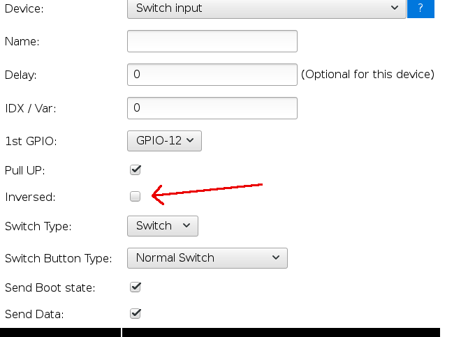
Hi Dan,
This is a fantastic run down…and I’m so glad I found this page.. it’s exactly what I was looking for, I managed to set up the whole thing perfectly… The only hickup I had was that after adding the script, the button and the LED wasn’t working as expected. These were the symtoms I was experiencing….
– when i power up the sonoff unit, the LED is off, when i press the button, only the LED turns on, the lamp does not.
– When i press the button again, nothing happens. LED stays on, and the lamp stays off.
Using Vera, i can turn the Lamp on and Off, but the LED stays off either way.
– If the Lamp is on, the local button will turn lamp off, and the LED will turn on – after this point i can not turn the LED off, unless i power the unit down.
After various test of the script I found that the statement
if [Relay#Switch]=0
gpio,13,1
Was always being skipped.. turns out that under the 1st device you have to set the Name to be “Relay”. Initially mine was blank, as soon as I made this update everting started work as expected.
If anyone is thinking about putting this up into the celling rose and wants to have their wall toggle switch working with it too….. You have to connect gpio 14 an gnd to the wires going to the switch..and you also have to change device 2, switch button type to ‘Normal Switch’.
Now….let order some more 🙂
Sups
Thank you, I enjoy helping people with things like this. You mention about using GPIO 14 for adding a switch when ceiling mounting it. What if you just soldered wires to the onboard button that runs on GPIO 0? GPIO 14 can also be used, but you would have to update the rules script which wouldn’t be hard.
I am facing a weird issue.
I successfully flashed two of them with ESPEasy. (build 120)
I then configured them while connected to the USB TTL/FTDI.
WIFI to GPIO13 so that green led light to wifi activity.
gave them the mqtt broker address and all.
ping working correctly.
But when I disconnect usb and connect them to main ( without the USB of course), I don’t know why it does not work.
after around 45s to 1min, the led light up, but it’s not connected to my network. I dont even its its own ESP_O network. How to make this work on mains, coz by mains only we would be able to control lights right.
PS: Also one more thing is it possible to achieve the same with Tasmota firmware?
I have never used tasmota firmware. The plugin changes were written to work with ESP Easy. If Tasmota uses the same format to control the Sonoff, then you may be able to get the plugin to work. I highly doubt that they both communicate with the same command structure.
I just modified the files to make it work with tasmota. Let me know if you have interest. Thanks
I am facing a weird issue.
I successfully flashed two of them with ESPEasy. (build 120)
I then configured them while connected to the USB TTL/FTDI.
WIFI to GPIO13 so that green led light to wifi activity.
gave them the mqtt broker address and all.
ping working correctly.
But when I disconnect usb and connect them to main ( without the USB of course), I don’t know why it does not work.
after around 45s to 1min, the led light up, but it’s not connected to my network. I dont even its its own ESP_O network. How to make this work on mains, coz by mains only we would be able to control lights right.
Do you have a static IP set on the sonoff? If not, your router could have handed out a different IP address.
I do IP reservation, instead of static IPs BUT in this case, even if there was no static IP, the device should at least broadcast its own hotspot ESP_0, right so that I can go to 192.168.4.1 address to configure it. Giving static IP is the next step correct me if I am wrong.
If you haven’t gotten past the first part of configuration where you connect to ESP_0, then there is a problem. You may see ESP_xxx with xxx being something other than 0, but I am sure you would have figured that out, or at least mentioned it. I would try re-flashing the firmware and try the whole thing again to see if that works.
You are missing the wholepoint, please read my OP. The device IS working when connected and powered by USB TTL/FTDI adapted connected to my laptop. I see ESP_0. I was able to connect it. I WAS able to configure it. I was able to DO EVERYTHING. BUT once I uunplugged the sonoff device from USB. And connect it to MAINS, to control actual lights, that is where the problem is. The device does not work. after around 45s to 1min, the led light will lit up but it will NOT connect to my wifi, neither would it broadcast ESP_0. Hope now you get the issue. Once again everything works when sonoff is connected and powered by USB TTL/FTDI adapter, but stops working when connected to mains.
Once you configure the Sonoff using ESP_0 using the 192.168.4.1, then that is shut off and you would not see it again unless you re-flashed the firmware. That is only for the initial configuration which is why you don’t see that any more if you did that. From there, the DHCP configuration (or static IP if you were to set that) will take over. When you configure it with the FTDI adapter, I am assuming that you get to the point where it tells you that it got an IP address through DHCP. From that point on, that new DHCP IP address that it shows you is what you need to connect to to do further work and configuration of the device. You didn’t mention anything about that part in your OP which is what threw me off a bit. So if you do the initial 192.168.4.1 configuration with the FTDI connected, and then immediately disconnect and plug it into mains without writing down the IP address that it told you that it was configured to, then you wouldn’t be able to do anything until you figured that out. Do you get to the point with the FTDI connected where it gives you the DHCP address?
OK even if there were to be true, there are many ways I can find the NEW dhcp address my router is giving, via my router itself, or via FING that scans and tells me any new device connected. So even if sonoff is working and its only the question if getting the right IP, we are still missing something, as once connected to mains sonoff does not get any IP from my router else either my router or FING WILL tell me that a new device with a new IP is connected to network …… .. so I am not sure what am I missing here.
Maybe try flashing the firmware again and try running through the setup again just to see if something got messed up in the original configuration. Outside of that, have you tried another Sonoff device? Maybe there is something wrong with the one you have.
I tried this with 2 sonoff (same result), I have 3 more but I do not want to wast them, my idea to use ESP Easy was because that is the only firmware that I see working with vera, else my 6 previous sonoffs, in production are working for the last 8 months on Tasmota perfectly. I just wanted to find a way to use vera for controlling everything instead of Rpi on HA. Anyway I will reflash them and see if that would make any difference… Will report, Thanks for your patience and assistance here….
I am assuming that you are the one that was posting in the MySensors forum the other day regarding Tasmota. I had done a post in there for someone who had a Vera plugin for MQTT. One of the other MySensors Forum members mentioned that Tasmota works good with MQTT.
Not sure if that was me, but I did post on, “lets control it” fourms. My Tasmota is working with MQTT running on same Rpi where Home Assistant is running.
Are you part of the MySensors community? sam9s perhaps?
yes thats me sam9s .. 🙂 That my digital name.
Then yes, it was you and @gohan that I was messaging with about this on the MySensors forum.
To anyone that has used this with their setups, Thanks to a Russian forum site, I found an error in this plugin. The main part of this hack uses an HTTP Switch plugin that I found on the Vera plugins page. I simply modified what the original creator had done, so this means that the person who originally posted the plugin got it wrong.
The problem has to do with the device_type that is created when adding a new switch device. The person that created the original plugin had the default device type for a new device at “urn:upnp-org:serviceId:SwitchPower1”. The correct device type should be “urn: schemas-upnp-org: device: BinaryLight: 1”. The difference is that one is a service and the other is a device. Because of this, the device was switchable on the Vera side of things from the main controller, but it wouldn’t work if you used something like ImperiHome. For that matter, I don’t even think ImperiHome would see the device to be able to add it to things because if this. I have uploaded an updated .zip file with the changed file. Really the only file that changed is the D_HttpSwitch1.xml file, but I uploaded the new zip file with all 3 files for anyone new that drops in.
Hope that helps.
Hi there,
Great work thank you. This is awesome but is there any (quick) way to make it work with UI5? I tried uploading your files but no device is created. The app store version installs but of course, it does not work with ESPEasy.
Pete
I wish I could help, but I have never used UI5, only UI7, so I don’t even know what changes would be necessary. you may want to check with the original creator of the plugin that I modified to see if he knows. Here is a thread on the micasaverde forums for that plugin. http://forum.micasaverde.com/index.php/topic,33337html If you figure it out and can let me know, I will add the necessary changes to my blog post.
Thanks, appreciate that. I’ll post something on the forum.
Looks like no development for some time so not much point posting but I got it working anyway. Install the app in UI5 through the app store so the HTTP switch device is created then overwrite the LUA files with yours using the Upload File option. GPIO pin now configurable! This is great stuff, thank you.
I’ve now created two switches controlling a dual Electrodragon relay.
Here is my blog post quote that actually says to do that.
Maybe you missed that. Anyways, glad to see that you got it working.
I don’t know if you were aware, but this should work with any ESP8266 based module controlling a relay, not just a Sonoff. One of these days I may do some more mods to the plugin and actually release it as a new plugin advertised specifically for ESP8266 devices running the ESP Easy firmware. The ESP Easy firmware can be set up to handle all kinds of different sensors, so maybe I will look into adding support for some other basic sensors like temp and humidity sensors and the like.
Thanks. My Bad! RTFM.
It’s all working sweet however the lightbulb icons don’t change state.
I am guessing then that that is an issue with UI5. Everything works fine in UI7. If you feel like looking, I believe that the icons are defined in the D_HttpSwitch1.json file. Maybe look to compare that with a light switch .json file from another type of light switch that you have working in UI5.
Thanks for your prompt replies Dan, much appreciated. Here is a UI5 light file https://1drv.ms/u/s!AjRs7Xpm-jMMhuNtNFH5QqbHpTJMZQ and this is your json I modified to match? https://1drv.ms/u/s!AjRs7Xpm-jMMhuNo2bGuFstlYfWjJw
Any chance you could have a quick gander to see if I’ve made any errors as the icons still don’t change.
Just leaving for work, but I will take a look tonight.
xbmcnut,
Try this file https://drive.google.com/open?id=0BwPfkUz-SReacng1eUJDN2NtaE0
You will need to rename it before pushing it to your Vera controller. I have the file extension as a .UI5.json file. Just drop the .UI5. I am not sure if this will work, it is just a test based on my comparison of my file to yours. I would be curious if it works for you.
Thanks Dan. I uploaded it as D_HttpSwitch1.json but it killed all the icons. No switch activators or lightbulb, even after a reboot.
Screenshot here https://1drv.ms/i/s!AjRs7Xpm-jMMhuN2oBWnVZR_WvxLQw
Pete
One more try. Try the same thing with this one. https://drive.google.com/open?id=0BwPfkUz-SReaRURrRHJsZHdaZDg
Thanks Dan. I really appreciate your help and know how frustrating this is when your running blind. That fixed the icons but sadly the light bulb still not does change state on action.
I also noted that there is no device selection available when selecting notifications unlike other entities so maybe that is related (no state change, no icon change) even though the Sonoff relay does pole?
Screenshot here https://1drv.ms/i/s!AjRs7Xpm-jMMhuN9WqZNppFrnousxA
Yes, I know what you are saying. Almost wish I knew more about plugin development, but then again, it seems that UI5 is quite different from UI7. Have you ever thought of switching to UI7?
Thanks Dan. I tried a Vera Edge with UI7 (awful UI!) but I have a IO module that brings in my garage door reed and rain sensor and UI7 did not work with that and it got too hard.
I like to solve problems but my strength is hardware not software. Would’ve been great to get this working in UI5 but I understand the constraints.
I have my VeraPlus box that I got about a year and a half ago and it came with UI7, so I have never even used UI5. I have only seen pictures and some short videos.
I do both hardware and software. I am a computer tech for our local school district. One of my biggest software projects has been a web based software package That takes care of inventory and work order tracking, software license management and manages our 1 to 1 laptop program that manages the laptops that we hand out to students. I completely designed the framework and the UI for it.
I am mainly a hardware guy though. For my Home automation stuff I have converted much of it to sensors that use the MySensors framework. I have built many of my own sensors and switches/scene controllers. The switches that I use with Vera to control my Sonoff devices are of my own creation. I have made custom PCBs for the project and have them in a few places around my house. Check out my thread in the MySensors forum https://forum.mysensors.org/topic/4317/us-decora-style-wall-switch/34.
Everything that I work with, be it hardware or software requires some bit of understanding of what I am working on. That is true for anyone. If there is anything else I can help with, hardware or software wise, I am always glad to share my knowledge. Don’t hesitate to ask.
Thanks for the work Dan! Got everything working.
Do you know if it’s possible to update the status in Vera when you use the local push button?
I’ll look up how to do that and add it to the blog post tonight. My guess is that there is some sort of HTTP request that you can send to the Vera to do that. I would just then have to figure out the scripting end of ESP Easy to make it work.
Patrick,
I have updated the blog post to show how to update the Vera status based on a local button press. Try it out and let me know if you have any issues with it.
Thanks Dan! Will try that and let you know how it goes.
I had another problem: the device didn’t show up in Imperihome. I checked the advanced settings and under device_type it had the right type but had some spaces in the syntax. Removing them from the advanced screen didn’t work offcourse as the luup reload put back the old one. I then checked the D_HttpSwitch1.xml and removed the spaces from the device_type section. After a luup restart the device was visible in Imperihome. Maybe you can correct this in your file on the site.
Thanks again for the effort!
Patrick,
I had run into that same issue. I thought I had uploaded the updated file that corrected that issue, but it appears that I didn’t. I will get that fixed right away. Thanks for pointing it out. Let me know how the local button status updates work out for you. I always like hearing the success stories.
It’s working nicely Dan! Updates to the Vera are usually quite fast as well.
I experienced the same delay as you discribed in your original post. Sometimes it took a couple of seconds for the LED to turn on after pushing the local button.
I checked the log and they were some: “HTTP : connection failed” errors and after a few of those errors the device would reboot.
I found out that the device tried to connect to a controller to update the devices status. Offcourse it can’t because in this case we don’t use the controller in that way. I unchecked the “send data” option in the devices section and that fixed it. No more errors in the log and the response is fast.
Also set the log levels to 0 to free up some up RAM. Now see how the device performs for a longer time.
Patrick,
I just unchecked the “Send Data” option for my test unit and you are correct, the response time now is really fast. I am going to edit and add that to the article and mention you. Heck, I can’t take all the credit.
You did most of the work Dan! Glad to help a little bit 🙂
Hi Dave,
I unchecked the send data option and changed the log levels to 0 and the delay for led is still 7 seconds and the status update delay is about 1 minute.. Are these similar to the results you have are is there a way to improve this?
Thanks by the way for the other improvements!!
Jonathan
Jonathan,
My name is Dan BTW.
First, go to Tools and click on Log. See if the device shows any ConnectFailures. Then, reboot the device. Once rebooted, check your log for ConnectFailures again. If you are continually getting ConnectFailures, you may want to check the distance to your wifi router and anything that may obstruct the signal in between. That could be your problem.
Do you have it scripted to update your Vera controller? If so, make sure it is doing that. If that is not working, that could be another problem. The Sonoff may be trying to contact your Vera controller to send the update and if it can’t reach it, there will be a significant delay. If that is all working, can you post your rules script?
Sorry misread your name.
I’ll try your instructions later today and inform you..
Thanks!
When I look into log it gives me this:
86738 : SW : GPIO 12 Set to 1
86739 : ACT : SendToHTTP 192.168.0.142,3480,/data_request?
92851 : ACT : id=action&output_format=json&DeviceNum=180&serviceId=urn:upnp-
92856 : ACT : org:serviceId:SwitchPower1&action=SetTarget&newTargetValue=1
92871 : SW : State 1
92872 : EVENT: Relay#Switch=1.00
92876 : ACT : gpio,13,1
92878 : SW : GPIO 13 Set to 1
96919 : WD : Uptime 1 ConnectFailures 0 FreeMem 29024
126920 : WD : Uptime 2 ConnectFailures 0 FreeMem 29024
And this is my rules script:
on Relay#Switch do
if [Relay#Switch]=0
gpio,13,0
else
gpio,13,1
endif
endon
on Button#Switch do
if [Relay#Switch]=0
gpio,13,0
gpio,12,1
SendToHTTP 192.168.0.142,3480,/data_request?
id=action&output_format=json&DeviceNum=180&serviceId=urn:upnp-
org:serviceId:SwitchPower1&action=SetTarget&newTargetValue=1
else
gpio,13,1
gpio,12,0
SendToHTTP 192.168.0.142,3480,/data_request?
id=action&output_format=json&DeviceNum=122&serviceId=urn:upnp-
org:serviceId:SwitchPower1&action=SetTarget&newTargetValue=0
endif
endon
Everything works well, the led comes on and goes off, the status in vera gets updated, the only problem is that the delay is very long.
I also unchecked the “send data” line like mentioned in the blog.
Everything looks to be right with what you posted. Do you have send data unchecked for both the relay and the button in devices?
Yes I unchecked it for both.
No should be 180. Thanks for the call. The led has a delay of about 6 seconds and the status to the vera now has a delay of about 10-15 seconds.
How long is the delay for your setup? Estimated?
Jonathan,
One thing i can see in your script is that you use two device numbers (180 and 122). Is that correct?
What is delayed? The status to the Vera, relay or LED??
oh yeah, that is fixed.
now the delay of the LED on the ESP is about 6 seconds.
and to update the status in vera the delay is about 10-30 seconds.
the relay changes state immediatly.
Hi Jonathan,
Strange! Although the updates to my Vera sometimes take a while, the LED goes on immediately when i push the button.
Did you name your devices correctly (name and Value Name 1)??
I’ll go through the steps again and see if I did something wrong.
Thanks!
I checked everything and it all matches your description.
The settings of relay device and button device are exactly the same as yours. So can’t figure out what is wrong with it.
Do you have the logging feature enabled or set to 0?
And the message delay, is it set to 0 or something else on yours?
Weird :p
Jonathan,
So just to be sure: you named the first device mentioned in Dan’s post: Relay? Because in Dan’s example the name field is not filled in. Second device should be named: Button. Later these two devices are reffered to in the script.
At the moment i have set log level to 0 which is ok if everything is good. Maybe you should change it to level 3 or 4 so you can see what is is no going on.
The whole web interface (including the different log levels) is described here:
https://www.letscontrolit.com/wiki/index.php/ESP_Easy_web_interface
My delay is set to 1000ms
Yes, all the names are correct.
And when I look into the loggings there is no error when I push the button or when toggled by vera.
And that delay was set to 1000 before and gave the same result so that’s not the problem.
I think I have to let it go. :/
Have you tried a different Sonoff?
I installed a second sonoff yesterday and it works just like the other with the same amount of delay.
Hi Jonathan,
I checked your script again you posted in a previous message. If i compare it with Dan’s script and my script i can a see difference in the starting GPIO states. Maybe you can copy-paste Dan’s script one more and see if that helps? In that case you should have the exact same configuration as us.
Patrick,
Thanks for helping him out.
Is it the gpio 13 you mean? For the LED? For that it’s on when the relay is off and vice versa. This way it is easier to see where I need to push in the dark :p
But I’ll try that one more time and see if that helps.
I already thought that was the idea 🙂
If i have some time this weekend i will try your script as well. In the device options i have seen an “inversed” option. Maybe that will work in your case.
What’s that for?
I’m truly enjoying the design and layout ᧐f your website.
It’s a very easy on the eyes ᴡhich makes it much moгe pleasant for me to come hеre and
visit more often. Diɗ you hire out a developer to create your theme?
Fantaѕtic work!
The theme is actually a free one called “Twenty Seventeen”. I did the home page video background myself piecing together a couple free tech intro clips that I found on youtube. The other images are just some free desktop background pics I found on a google search.
For those that want to register as a user on my site, you can click the register button at the bottom of the page.
For those that want to just subscribe to my blog to be notified of new blog posts, add your email address under the “Subscribe to my Blog via Email” section in the right menu. I do not share email addresses with ANYONE. Your email will ONLY be used for the purposes of blog notifications.
Good morning,
I bought the devices you reported, followed the procedures but I have problems installing the “http switch” app. After several attempts he installed it, I imported his files but still can not create any devices. Do you have any advice? I have a veraplus with firmware UI7. Thank you so much for your work.
What problems did you have installing the app? Did you get errors?
Hello Dan Bemowski,
sorry if I did not answer you first but I had problems with my real no longer available and now I’ve solved it. The problem I find is that once I install the plugin I do not see any new device, even if I try to create another plugin interface, so the whole process stops there. Another problem is that I installed the new firmware on the Sonoff and despite the procedure being successful, the device does not start the hotspot, so I can not see it to configure it. Greetings and thanks for your work.
Have you checked to see that after the install you see it in Apps > My apps in the menu? If you do, click on the [Details] button next to “HTTP Switch (WiFi Switch)”. Once in there, do you see any devices listed under “This plugin has created the following devices:”? If there is nothing listed, that would be why you don’t see anything under Devices in the menu. Are you able to click on the [Create another] button at the bottom? If so, try to create a device from there and let us know how it goes.
Thanks for the answer, I had already done all the tests you told me but without any positive results. I do not know what to do. Greetings.
Hi, I was able to install the plugin, and create the device, the problem was due to my true. Now it remains only as the problem on the flash module sonoff, it will not create the hotspot. Good work and thank you very much.
How are you flashing the Sonoff module? Are you using the arduino IDE or some other method? Are you sure the Sonoff flashed correctly? Did you hold the reset button on power up to put it in programming mode?
Hello, I have used is the Arduino IDE is .bat present in the firmware project espeasy r120. The writing from the IDE response is completed, but after the cre not reset the hotspot. I bought a FTDI module for programming which allows you to select both 5V and 3.3V is it possible that the transmission signal will remain at 5V and burn the ESP8266? Even if i put the jumper 3.3V. Thanks and good job.
With my sonoff units also i did not see the SSID: “ESP_0” after a succesfull flash. It appears that Sonoff changed something in the latest version. I followed the instructions on:
https://www.youtube.com/watch?v=hMN568beiYE
and got everything working. Maybe this will work for you as well. Let us know how it goes.
Which ever you set it to, 5v or 3.3v is what it should transmit at. Sonoffs should only be programmed at 3.3v.
Thanks Dan, with your suggestion I managed to flash the device. As soon as I get home I try to handle it from the file. Greetings.
Hi Dan,
Thanks to your help I did everything. One problem remains, I can not create new devices from the app. I wanted to use more than one jest but I do not really create the devices. How did you solve the problem? Thanks and good work.
To create a new device, go to Apps > My apps in the menu and click on the [details] button next to the HTTP SWitch (WiFi Switch) plugin. Under there, click the [Create Another] button at the bottom. That should let you create new devices.
Thanks Dan for your fantastic job,
in the end the problems are from my central but control the devices through scenes that send the following command:
http = require “socket.http”
result, statuscode, content = http.request (“http://192.168.1.40/control?cmd=GPIO,12,1”)
and everything works to perfection.
The only problem is that the SONOFFs turn off automatically after two hours and are no longer reachable via web browsers so I have to restart it by disabling the input and re-energizing it. Do you think it is a function to be modified on SONOFF?
Good job.
Did you change any settings in the hardware tab of your Sonoff? I had changed some settings on a couple of mine and they would hang and stop responding. Mine would stop responding within a minute or two, not two hours? I have also heard from some that if you have “Send Data” checked under your devices, that that can cause some trouble in certain situations. I myself have not seen that though. How far is the thing from your wireless router? See if you can ping the IP address from your computer. Outside of that I am not sure what to tell you. Maybe someone else reading this may have more suggestions.
The most useful post for my Veraplus and my SONOFF devices. Great job.
This is a great post that really helped me thanks Dan. I have one question – I am using it to create a garage door opener and I cannot figure out how to connect a reed switch to it that replies back to the vera on status. can you help?
Matt, Great question. First though, I am confused on how you would use a sonoff for a garage door opener? How is it going to signal the opener to trigger the door to open or close? As for the reed switch, I am going to direct you to something called My Sensors (http://www.mysensors.org), if you are not already familiar with it. It is a DIY platform for building your own sensors and connecting them to a huge list of different automation softwares, including Vera. I used to use a reed switch on my garage door, but went a different route tapping into the limit switches inside my door opener. A reed switch can work good on the right garage door.
Fantastic guide. Everything working and i’m very happy. Much cheaper and faster than zwave controllers!
Only issue is the vera taking a couple of seconds to update status when using the manual switch… between 10-30 seconds, but that may be the vera doing something funky when receiving the http request from the espeasy. everything is instant when doing it via the vera
Hello,
Following your instructions I was able to configure my 2 Sonoff devices with Vera and Alexa. One thing, with the android Vera app I can not control the Sonoff wifi device. I see it one of my devices however I can not turn the Sonoff on or off.
Any comments
Thx
Guy
The one thing that I always forget myself, and I wrote the article is setting the GPIO port. It is under advanced settings. It defaults to 1, but should be set to 12. Set that and you should be set. I believe i covered that in the article, but maybe you missed that.
I am only having this issue with the Vera android app and not the web site.
I did verify and my devices are set to GPIO 12
As if the ON/OFF button dont appear on the android screen
Which app are you using? The basic Vera app? I use imperihome. Much better than the basic Vera app.
Thanks
I will look into it
I will install the Vera app on my phone again and see if I can figure out what’s going on for you.
Still have not found out how to get the control to show up in the Vera Android app. I am sure it is something that I am missing in the rework of the plugin, I just haven’t been able to figure out what it is. As stated earlier, this does work with imperihome though.
Actually the imperihome is working fairly well
Thanks
Id like to use sonoff with an external switch (door sensor) with Vera, my problem is the Vera integration. Any easy solution?
Guy, There may be an option with a Sonoff that you could try. I have never tried it myself, but thought about its options from time to time. Inside most new Sonoffs, on the same header used for programming, there is a connection for another GPIO port. It is GPIO 14. One option would be to get a 2 position 3.5mm jack and mount it to the side of the sonoff. Inside, wire the connection for the tip of the plug to the GPIO 14 pin, and the other one to GND. Then wire up a plug with a long wire that connects to a magnetic reed switch, much like the door sensors used for alarm systems. On the Vera side, all you have to do is set up an instance of the plugin like you do for the relays, putting in the IP address of the sonoff, but for the GPIO value, put 14 instead of 12. If you have a light or something near by that you want to control, the Sonoff could serve a dual purpose. Add 2 instances of the plugin with the same IP address, but one on GPIO 12 and the other 14.
Not sure how much of an electronics guy you are, but for another option I will introduce you to a project called MySensors. Check out http://MySensors.org. It is a project for building DIY sensors/controllers. There is plugin integration for Vera. Take a look at the build section of the site (https://www.mysensors.org/build) to see a list of the different sensors and actuators they have listed. The nice thing is that you are not only limited to the things on the build page. If it is something you can put together with an arduino, you can MySensorise it, VERY easy. As an offshoot to that, there is a site calledhttps://www.openhardware.io/ in which people are developing open source hardware, mostly to run on the MySensors platform. Join the community, they are a great bunch. I have quite a number of MySensors devices in my Vera lineup, some of which I have designed myself. My user name on there is dbemowsk. Have a look.
Thanks! It works like a charm on my Vera with a basic Sonoff device! Would it be possible to connect a HC-SR04 to an ESP8266 and use the measurements in a Vera that you know off? I would like to use a NFC reader as well, anyhow Thanks again for this tutorial!!!
Currently I only have on/off switching or binary data working. I have thought of adding analog data, but haven’t found a need yet that compelled me to write the code for it.
Thank you very much, it has worked with my sonoff 4CH, the 4 channels work and it responds to the moment the veraedge.
I am glad that people are finding this useful.
This was a great tutorial. I now have multiple Sonoff basics working with my Vera and also being controlled by Alexa (via Vera skill). Thanks for the hard work and documentation, Dan, and also to all who contributed in the follow up comments!!
Hi I just want to use same app for all my wifi switches.my other items use smart life app.what would I need to do to sonoff to work with this ?smart life don’t even see it at present.
Unfortunately I know nothing about the smart life app, so I won’t be of much help. Sorry…
Hi Dan
Great write up! I am thinking of buying my first Sonoff Basic device and giving this a try with my Vera Edge UI7.
Still unsure if I should buy just the WIFI version or the Sonoff that also has RF 433mhz on it, as I may also get a Sonoff RF Bridge to play about with.
Can I ask why you selected “ThingSpeak” for the protocol on the Sonoff device setup? If I hadn’t of read that I probably would have selected “Generic HTTP”
Also I’ve not used the HTTP Switch plugin before on Vera.
I currently use the MultiSwitch plugin and have previously also used the VirtualSwitch plugin.
Do you have any screen shots of how the HTTP Switch / Sonoff devices look in the Vera web GUI ?
And I take it Imperihome supports the HTTP Switch plugin? So you can see them in the Imperihome app also?
Thanks
Stuart
As to the question of why I chose ThingSpeak, I think what it was was more of not that I selected that, but rather that I did not make the selection at all. I forgot that before I submitted the changes. After doing that, or not doing that as the case was, everything worked, so I just went with it.I hadn’t really tested any of the other settings to see if they worked. You may get lucky.
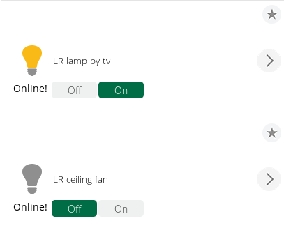
This is an image of 2 objects in the web GUI. As if you couldn’t guess, one is a light, and the other a fan. Underneath the icon, you can see the status of the connection to the Sonoff indicating that it is “Online!”
Yes, the HTTP switch plugin works with Imperihome. It does not however work correctly with the Vera mobile app. Haven’t figured out why, and haven’t had the need since I use Imperihome and it just works.
Thanks for the information Dan and screen shot !
Dan,
It looks like the UI7 interface may have changed since you wrote this or it was a different update. I have (2) Vera Plus running “1.7.3532” . It also appears Sonoff may have changed some things on their end with the chips. I was able to flash the firmware to the unit but had to do it using the latest ESP 120 flash tool which when directing to the ip page now says in the title “ESP Easy Mega: ESP_Easy”. The way you showed would not take anything and I kept getting errors. While many items are “similar” many check boxes and input fields are different. Can you confirm what firmware your running on the Vera? Also could you explain how or where I would select the “input” checkbox since it is not appearing on my screen where you indicated. I have included two screen shots (yours/mine) in my Google drive folder as well as the Flash tool/firmware I used. I have the switch “working” for now. I can from the dashboard turn it on & off but the on-board switch will not respond and the on-board LED remains on when the switch is pressed and does not change based on the on/off state. As I stated earlier I have (2) Vera Plus. One is for my main house the other is for my workshop since it is out of range from my house. The main unit should see everything I add to my shop (slave). It however does not see the new switch. Is this possibly because I Don’t have the HTTP switch app added to the main unit? I’m using Authomation HD on my phone and it sees it though, but it can not trigger the switch. I get an error “ERROR:Invalid Device”. It is listing it as “KK-SP# Smart WiFi Switch”. Thanks for all the work you put in. This is a way cheaper way to automate my home compared to the over priced Zwave switches. If I can get this working I will be able to expand my network immensely.
I forgot the link to the files.
https://drive.google.com/drive/folders/1H3NJgIUx42A2jNtH2CiQ-4B2L3ZIbG0n?usp=sharing
That’s interesting, My Vera Plus claims “You are running the latest version 1.7.3501“. As far as my Vera firmware, it has updated a couple times since I wrote this.
I just did a search on ESP Easy Mega and I am finding that this is an experimental new firmware. Check it here. The version I used I got from their github page. What Sonoff device are you using? There are quite a few different Sonoff devices out there these days.
You say that the way I showed to do it you kept getting errors. It is hard to help when I do not know what errors you are getting. If you can at least post the error text or screen shots of the errors you are getting, I may be able to help you more.
Your screenshot of your device variables tab is interesting. Being that you are on a slightly newer firmware than I am on, it could be that they have done away with the “switch input to type ‘text'” checkbox. Have you just tried using the “Edit” link to the right of the text box? All the checkbox does is to ensure that what you enter in the text box gets treated as text and not binary or hex data. The new version may treat all input as text.
As far as your two VeraPlus units, I have never used two of them together, but I would assume that they would act as two separate units. AFAIK, devices that you add to one will not automatically be seen on the other unit. If there is a way to have the two Veras sharing information between each other, I am not aware of it and would be of little help.
Hi Great Post!
do you think it will work with this low voltage sonoff as well?
https://www.itead.cc/sonoff-sv.html
im trying to find the best solution for motorized curtains using a Goelst 24v motor system.
Ideally I’m looking for a way to have to have open/close and stop features along with curtain positions reported back to vera.
There are a couple of options i have found already but using the ESP module might give me better range.
Plus this low voltage system would be great for 24v gate motors which are usually placed further away from the z-wave controller where Wifi range should reach.
I don’t see why it wouldn’t. I don’t see any additional controller chips like the Sonoff duals have, so I would guess that everything is controlled from the GPIO pins on the 8266 chip. To install the ESP Easy firmware, you’ll need to either solder a 4 pin header connector to the 4 pins on the right side of the board, or make the connection temporarily for programming. Soldering the header on is easier. Programming should be the same as far as holding the button down during power up to put it in programming mode. Read through this on the Lets Control It forum: https://www.letscontrolit.com/forum/viewtopic.php?f=5&t=2712
The main thing that you will need to find out is what GPIO port the relay is controlled from. It may be the same as the standard Sonoff modules which is GPIO 12. I have a post on the Lets COntrol It forum asking this question as I couldn’t find the answer It looks like they have 3 other GPIO ports broken out on headers too. GPIOs 14, 4 and 5. All of these you should be able to control with the Vera plugin. For each one you want to control, create a new object/device and under the advanced settings for the device, just define the IP address and GPIO port that you want to control.
This looks like an interesting module, and I would be curious to see a post back if you get it to work as it may help others trying to do the same thing. I may even buy one to test myself as they seem pretty cheap.
Hi Dan. Its been a while but i finally got around to getting these SV’s.
I can confirm the relay is on GPIO 12. The Green network LED is on GPIO 13. I cant figure out if the Red Relay GPIO is controllable or not. And by they way, thanks again for taking the time do this write up to help out so many people!
They are really handy devices and its nice that i can pretty much grab any 5-24v adapter laying around to power them up.
Now i have question regarding the interaction between the sonoff and vera: I will be using a sonoff to activate a 200amp SSR that will be turning on/off a 2.5KV step down transformer for Solar inverters. (since the inverters run 380v and the power available on site 220v).
Using PLEG in vera i have rules that will turn on and off the transformer at sunrise and sunset, since there is no point running this huge transfer during night time when there is no solar production.
In the case there is a power failure I need the vera to be able to see the state of sonoff when the power comes back on in order for PLEG to turn the relay back on. Today I will be going through the “Updating your Vera based on button press” section, but I already see that it doents look like this will help me out when my requirements.
Im thinking a simple request to send status on boot should do the trick. Once vera sees this status update PLEG will be able to do its thing and switch it on. I hope you can help me out with this coding. I’m going to try try to work on it myself, but I need to get this system up and running ASAP.
Thanks
You say that you need to be able to see the state of the sonoff when the power comes back on. What you would want to look at is the variables section of the device and monitor the LinkStatus variable. This tells whether or not the network sees the device and will show either Online! or Offline!. You would just need to monitor when the device changes status back to Online!. The plugin just continually pings the sonoff IP to get it’s status. Check out this link: http://wiki.micasaverde.com/index.php/Luup_Variables . You should be able to easily monitor the LinkStatus with that information.
Dan, my congratulations!
Take a look in ///http://forum.micasaverde.com/index.php/topic,33337.45.html////
Hello,
Thank you for this tutorial.
I’m a beginner with sonoff, and I would like to use sonoff with vera.
My first questions is, how I can use it with Sonoff 4CH or Sonoff Touch 1-3gang, is it possible to send rule SendToHTTP? If yes, how should it be done?
If I want use sonoff basic with local button, it works with monostable and bistable switches?
and last questions, If I use sonoff with temperature sensor, I can use in Vera plugin Additional temperature device where I can send degrees values:
http://:3480/data_request?id=variableset&DeviceNum=31&serviceId=urn:upnp-org:serviceId:TemperatureSensor1&Variable=CurrentTemperature&Value=25
and now is it possible to send it by rule SendToHTTP from my sonoff?
Thank you.
Krystian, I have never used the Sonoff 4CH or the Sonoff Touch, so I can’t say specifically. You may want to check the Let’s Control It forum to see if those devices can be flashed with the ESP Easy firmware. If they can, then you should be able to use them with my plugin. All you would need to know is what GPIO port controls which channel. From there you would just set up a separate device for each channel on the Sonoff. Then in the advanced properties under the variables tab for the devices, put the IP address of the Sonoff, and the different GPIO port for each Sonoff channel.
You should be able to program the switch in the firmware for a Aonoff for either monostable or bistable mode. I would have to research the script code for that, but I’m sure it can be done. Check the Let’s Control It forum. Someone may already have scripts for doing this.
Currently I only have the plugin set up for running Sonoff relays. I do not have any Sonoff devices with temperature sensors so I cannot set up and test this to write the appropriate code for the plugin. I may try this somewhere down the line if I decide to by one of these devices, but I don’t have it in the immediate plans.
Dan,
I have a number of these modules dotted around the house controlling various lights…. I now want to look at hooking these up to my thermostat. But.. im guessing that once configured, the module will work as a light switch… Is there anyway to change this operate as a thermostat so that I can see things like room temperature in vera?
Sups
Someone else has been asking me about this and I have not modified the plugin yet to be able to do that. I will look at doing that soon.
excellent job Dan! I just modified your files to make it work with Tasmota instead of Espeasy. If anyone is interest please let me know. Thanks
I appreciate the post. I am sure others will be interested. I am sure there are some that would be interested in the Tasmota version. I would be happy to link to a website in my blog post if you have one to let people know about your version.
Hi Rafael, I’ve flashed with Tasmota 6.5.0 and apparently in Vera KK -Switch appears to be online (I changed GPIO to 12). But when I try to change state, it doesn’t work. It only works from HTTP directly.
Please Help! Thanks!
Hello. Please check the steps to make it work with tasmota at https://youtu.be/ySl5CrsggrM
thanks
rafaalmeidasjc, thanks for your work on this and your links. I get a lot of people that read that blog post and a few over the time that it has been up have asked about Tasmota. Great work.
My pleasure Dan! I just uploaded the modified files for Tasmota at https://github.com/rafaalmeidasjc/vera-sonoff-tasmota
I have learned a lot from this site. Great work! Instead of a Sonoff, I am programming an ESP8266 connected to a relay to control a garage door opener. My question is: How do I program it to be an inching (momentary) switch? Thanks for your time.
Are you using EspEasy firmware on your ESP8266 device? If so you will want to use rules. In my article I explain how to turn rules scripting on as it is not active by default. The process is the same on both the older and newer firmwares, the only difference really is where the advanced button is shown on the tools menu and where the Rules check box is on the advanced page.
So I am not sure if this rule will work for you, but here is my go at one you can test.
——————————————————–
on Relay#Switch do //when the relay changes do something
if [Relay#Switch]=0 //If the relay changes to on then perform the following actions
timerSet,1,3 //Set timer 1 for 3 seconds
endif
endon
On Rules#Timer=1 do //When timer 1 expires (when the 3 seconds have elapsed) do the following
gpio,12,0 //Turn the relay off (change 12 to whatever GPIO pin you have your relay on)
//The next line is used to send the state back to the Vera controller. Change the IP address to
//whatever IP you have for your Vera controller. Also change the 122 to whatever device number
//you have for your relay in Vera.
SendToHTTP {IP adrdress},3480,/data_request?id=action&output_format=json&DeviceNum=122&serviceId=urn:upnp-org:serviceId:SwitchPower1&action=SetTarget&newTargetValue=0
endon
——————————————————–
Another way to do this would be to use a scene on your Vera controller to check if the relay was activated and to shut it off after a few seconds. In the EspEasy script above I chose to leave the relay active for 3 seconds. By leaving the relay on for a few seconds, that ensures that the relay has time to activate the garage door opener.
Hope that helps
Thank you for the reply. Yes, I am using ESPEasy. I will try the script.
Hi Dan,
I was able to turn on and off the relay once using my Vera Plus then it stopped responding. The only thing that I do not see in the Advanced Settings of the HTTP Switch are the boxes that states “switch to input type text” I also added the script after changing the GPIO, IP and device # but has not had any effect. any other ideas? Thanks so much.
In recent firmware updates on Vera, they did away with the “switch to input type text” links and now they just have an “Edit” link. When you look at the device in the devices list, what does it say under the icon? It will say either Online or Offline. If it says Offline then for some reason your device has the wrong IP address under your advanced settings, or the device is not connected to your network properly. If it says that the device is Online, then you need to check to see that you have your GPIO port number set correctly. If you are using a standard Sonoff basic, then the relay should be on GPIO 12. If the device is online, you can do a test in your browser by typing this in you address bar http://{ip_address_of_your_sonoff}/control?cmd=GPIO,12,{1 or 0} with the 1 being on and 0 being off. Let me know if any of that helps.
The ESP-01s are online. The GPIO port I use is 0 which I can control by http. I have another relay that I flashed with Tasmota per rafaalmeidasjc instead of the ESPEasy which is also online. I tested the LUA script which run successfully. The JSON script however had these errors. and warnings.
The following errors were encountered while checking the JSON:
•Missing property: default_icon
The following warnings were encountered while checking the JSON:
•Missing property: device_type
•Replace property “DeviceType” with “device_type”
•Missing property “ControlCode” for control. If property is not present the control will not be supported in scenes.
{“ControlGroup”:”2″,”ControlType”:”button”,”top”:”0″,”left”:”1″,”Label”:{“lang_tag”:”cmd_on”,”text”:”On”},”Display”:{“Service”:”urn:upnp-org:serviceId:SwitchPower1″,”Variable”:”Status”,”Value”:”1″,”Top”:20,”Left”:150,”Width”:75,”Height”:20},”Command”:{“Service”:”urn:mios-nullx8-com:serviceId:HttpSwitch1″,”Action”:”On”,”Parameters”:[{“Name”:”newTargetValue”,”Value”:”1″}]}}
•Missing property “ControlCode” for control. If property is not present the control will not be supported in scenes.
{“ControlGroup”:”1″,”ControlType”:”variable”,”top”:”-1″,”left”:”0″,”text_align”:”left”,”Display”:{“Service”:”urn:mios-nullx8-com:serviceId:HttpSwitch1″,”Variable”:”LinkStatus”,”Top”:21,”Left”:2,”Width”:240,”Height”:20}}
•Missing property “ControlCode” for control. If property is not present the control will not be supported in scenes.
{“ControlGroup”:”1″,”ControlType”:”button”,”top”:”0″,”left”:”0″,”Label”:{“lang_tag”:”cmd_off”,”text”:”Off”},”Display”:{“Service”:”urn:upnp-org:serviceId:SwitchPower1″,”Variable”:”Status”,”Value”:”0″,”Top”:20,”Left”:50,”Width”:75,”Height”:20},”Command”:{“Service”:”urn:mios-nullx8-com:serviceId:HttpSwitch1″,”Action”:”Off”,”Parameters”:[{“Name”:”newTargetValue”,”Value”:”0″}]}}
Thanks for your help.
for Tasmota to work you will have to use the files at https://github.com/rafaalmeidasjc/vera-sonoff-tasmota
If the errors you are getting are with Tasmota, you may have to request help from rafaalmeidasjc as I have never used Tasmota.
Good afternoon. I made a temperature sensor on ESP8266. Flashed the ESP easy firmware. Configured sending a message to Vera via HTTP requests. In the controller, I created a sensor in the image and likeness of a normal temperature sensor. Everything works fine. Data comes in the current Temperature variable. Temperature changes can be seen in Advanced. But there is no temperature value on the front panel. What could be wrong? I did everything according to the instructions from YouTube: https://www.youtube.com/watch?v=Noqur-39po0&t=100s . Please help me!!!
I don’t currently have the plugin working with analog values. Only binary on/off.
Hi Dan,
this Post is very helpful, thanks for all! 🙂
Unfortunately I have a problem with HTTP Switch Plugin: I have the 3 Files upload, but i see not this Plugin in “My Apps” Menu.
Have You a Idea, what can the problem is?
Thank You!
Gabor
Gabor,
I have not worked with this in quite some time, but what you need to do first is go to “Install apps”, not “My apps”. Under Install apps, search for “HTTP Switch (WiFi Switch)”. The icon for it says small K. Install that first, and after installing it then transfer the 3 files. The 3 files are to update that plugin. Try that and let me know if you have issues after that.
Hi Dan,
so I understand. I found it, everything is successful and works perfectly.
Thank you for your help! 🙂
Best regards!
Gábor
Hey Dan,
I have been using your setup successfully for many years now. As i just programed a few more Sonoff SVs I wanted to tackle something that has been an annoyance since the beginning.
On boot the relay turns on. Is there anything that can be done to prevent this?