
So I decided to get my feet wet on creating my first commercially manufactured circuit boards to release as open source hardware. For one of my automation projects  I had built some custom in-wall automation scene controllers based on MySensors. The controller consisted of 3 boards; the power supply board, the computer board (Arduino Pro Mini) and the switch board (first prototype seen on the left).
  All three of the circuit boards were built on standard 30mm x 70mm prototyping circuit boards like these. My first fully assembled version of the controller can be seen below. Though the design seemed to work good, they were a bit of a pain to put together.
  Building one controller on prototyping boards and wiring it all up took 4 hours or more. After building 3 of them and seeing how they worked, I wanted more, but I didn't want to spend all the time making them. So, it was time to get my feet wet on PCB manufacturing.
The design
So I figured that if I was going to be making a number of these, I wanted the design to be flexible. I wanted to be able to do more with it than just a scene controller. Having the 3 separate boards made it modular. I figured I would design it so that I could build more than just switch boards for the face of the CPU board.
The main board
 For the design of the main board I broke out all digital and analog IO lines from the pro mini except for A6 and A7. I also have ground, raw 5 volt power plus the 3.3 volt regulated power from the pro mini available on 2 single inline header connectors. A4 and A5 on J3 also provide I2C capabilities to the front board. With all of these, the only limit to what can go on the front board is what you can fit in the small space..
The keypad board
 The design of the keypad board may look a bit crowded, but it was designed that way to make it flexible. Many different keypad designs can be made from this one board. I had gotten the idea for this type of design from a video I had seen by a guy in Australia named Jonathan Oxer. He had designed light switches for his house and designed a single universal circuit board that allowed him to use that one board for building different switch configurations. You can find the video here http://www.superhouse.tv/arduino-light-switches/ . His other videos on home automation are well worth watching. Check out his website here. The keypads can be made with or without indicator LEDs.


 The buttons can have any text embossed on them, or they can just be left blank. Here are just 3 examples of the many different wall switch designs that can be made using this board. No need to have separate boards printed when you want to put together a new switch. Just grab a board, print the switch layout on your favorite 3D printer and screw it together. Done!
The power supply
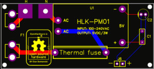 There is nothing fancy with the power supply board. It is based on the standard HLK-PM01 power supply module that will take a wide input voltage (90 ~ 264V AC) and convert it down to the 5 volts needed to power the controller. The output is filtered with a 0.1uf ceramic capacitor as well as a 10uf electrolytic to help stabilize the voltage supplied to the controller. On the AC input side, a standard 0.75A glass fuse as well as a 73°C (163°F) thermal fuse is used for maximum protection since this will be used in wall. You can never be too careful.
Conclusion
In the future, I will design other sensor boards to be used with this controller. This is an open source design, so feel free to take the gerbers and design your own sensors for it. I hope you like the design. Let me know your thoughts.
Related Images:


