Description
This post is to describe how I used Sonoff modules with my Vera Plus automation controller. I'll explain the configuration and setup of the Sonoff, as well as the modifications needed to an existing plugin to make the whole setup work.
Details
 Sonoff modules are cheap Wi-fi controllable relay modules that are based off of the ESP8266 chip. Here I will describe how to control these with a vera home controller. The procedures described here should work for nearly any ESP8266 based relay module and are not exclusive to the Sonoff modules.
The basic outline of the procedures are as follows:
- Flash new firmware to the Sonoff or other ESP8266
- Set up and configuration
- Testing the device
- Installing the necessary plugin on your Vera
- The configuration settings
- Adding local control using the button
- Updating your Vera device based on the local button press
DISCLAIMER: I take NO responsibility for issues or problems that may arise from using the procedures outlined here. I am merely giving the information on what worked for me on the devices that I have. The procedures may be different for other ESP8266 modules. Please consult documentation on the modules that you have for more information. It should also be noted that this will wipe out the existing firmware on the device and it will no longer be able to be used as originally sold.
Flashing firmware to the Sonoff or other ESP8266
The first step in this process is to make sure we have the correct firmware loaded on your device. The firmware that we will be using for this project is the ESPEasy firmware which is an open source firmware for ESP8266 modules. There are a few ways to flash the firmware to the device, but the procedures I will outline here for flashing this firmware to the device involve the use of the Arduino IDE. One thing you will need to do the programming is an FTDI USB to serial adapter. These can be purchased on ebay cheap. Lets get started.
The first thing you will need, if you don't have it already, is the Arduino IDE which can be downloaded from this link: https://www.arduino.cc/en/Guide/HomePage. Follow the installation procedures outlined on that page to complete the install.
Once you have the IDE installed, you will need to add the ability for it to flash the ESP8266 modules. To do this, got to File > Preferences, and just up from the bottom of the Window you will see a text box labeled "Additional Boards Manager URLS". In the box, paste this URL "http://arduino.esp8266.com/stable/package_esp8266com_index.json". You should now see some new entries in the list of available modules. The one we are concerned about for this post is the "Generic ESP8266 Module". Select that and the com port that you have your FTDI adapter attached to.
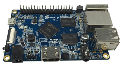
Next you will need to connect the FTDI adapter to the Sonoff module or other ESP8266 device. For the purposes of this post, I will only outline the connection to the Sonoff. It is easies to solder a header connector on to the Sonoff on the center row of holes as shown below. If you plan on flashing a lot of modules, you may want to make yourself an adapter cable to connect the FTDI adapter to the Sonoff. The cable should be wired like the diagram below.
Next you will need the firmware to flash. This can be downloaded from the SourceForge websit using this link: https://sourceforge.net/projects/espeasy/. In order to flash the firmware, you will need to put the Sonoff into programming mode. To do this, unplug the USB cable to the FTDI adapter, hold down the reset button (labeled GPIO0 in the image above) on the Sonoff module, then plug the USB cable in again. Now click the upload button in the Arduino IDE. The firmware should flash to the device. If for some reason it does not, chances are that you didn't get it into programming mode. Repeat the steps above and try again.
Set up and configuration
After flashing the firmware to the device, you need to do the initial configuration to get it to connect to your WiFi router. When a device with ESPEasy firmware starts for the first time, it will present itself as an access point. For the initial configuration you will need a tablet, smart phone, laptop or other wireless capable device. On your chosen device, go to your configuration screen for setting up WiFi. In your list of available access points to connect to, you should see one called ESP_0. When you try to connect to it, it will ask for a password. The default password is configesp.  After connecting to the device, go to a web browser and navigate to 192.168.4.1. This should bring you to the new device wifi setup page. This is where you will set the device up to connect to your access point. Select your access point from the list, and if your wifi is encrypted and requires a password, type that in and click connect. You should then see a page showing a countdown. At this point the controller is attempting to connect to your access point. If successful, your laptop, tablet or phone should automatically switch back to connecting to your regular wireless access point and navigate you to the IP address that the device picked up from your router's DHCP server.
You are now ready to perform the device specific configuration to define how you will connect to the device to your Vera. For my setup, I picked a range of IP addesses that I would use for my Sonoff devices. I made a list of my Sonoff devices and assigned them each an IP address. I left room in the pool of IP addresses I chose to have more room if I decided to add more of these to my setup. You can judge this based on your configuration.
Now, in the menu at the top, click on "Config". This will take you to the main device configuration page to define how you will connect to the device. Here we will start by selecting a protocol to use. I am not sure of the specifics for each protocol, but for my setup I chose the ThingSpeak protocol. You can ignore the Controller IP and Controller Port for now. Next we will set up the IP address for the device from the list that we made earlier. You will set this at the bottom of the page under "Optional Settings". All of these settings should be set as appropriate for your home network setup, but here is how I set mine up. Type the IP address in the box labeled ESP IP. Next you will need the IP address of your wireless access point which in most cases can be typed in for the ESP GW and ESP DNS settings. And last would be setting your subnet mask in ESP Subnet, which again in most cases can be left at the default of 255.255.255.0.
The last thing that you need to configure is how the device will operate. Since the ESPEasy firmware can be used on amy number of different ESP8266 devices, the firmware is highly configurable for many different types of devices. For the HTTP Switch plugin that we will be setting up with Vera, we are only concerned about configuring a relay for now.
In the top menu, click on Devices.  On initial setup, the devices page should look like this. Some things you will want to know prior to setting up the relay. The standard Sonoffs have the relay connected to GPIO 12. If you are configuring this for some other type of ESP8266 device you will need to consult any available documentation to find out which GPIO port the relay is configured on. Start by clicking the Edit button for device number 1. On the next page you will be given an option to select a device. For this select "Switch Input" since we will be controlling a relay.
  Once selected, you will be given a list of configuration options. The options we are concerned with for now are 1st GPIO, Pull Up, Switch Type, Switch Button Type, Send Boot State and Send Data. For the 1st GPIO, select GPIO-12 for the Sonoff relay. If you are using another ESP8266 device, select the GPIO that your relay is connected to. For the Switch Type, simply select "Switch" as this is a relay controller. Last is selecting the Switch Button Type which will be "Normal Switch". You should also make sure to check the box next to Pull Up since we will be using the ESP8266 internal pull up resistors. For my setup I have also checked the boxes for Send Boot State and Send Data. All other settings for now can be left at their defaults. Now click on Submit to save the new device configuration.
Now we will reboot the Sonoff by clicking Tools in the top menu and selecting Reboot. This will cause any changes to be loaded. If you made changes to the IP address on the Config page, you will most likely need to type the new IP address into your browser's address bar to access the newly configured device.
Testing the device
Prior to doing anything on the Vera side of things we will want to make sure that all of the work we did configuring the device is going to work. The ESPEasy firmware uses GET based control commands that can be typed into your browsers address bar. For testing we are going to use the command for turning on and off the device. You will want to have something connected to your Sonoff or other 8266 device to be able to see if the commands work. For me, I connected a small night light for this. The command format that you will use is this:
http://{your device IP addess}/control?cmd=GPIO,{GPIO pin},{1 or 0}
In the command above, replace {GPIO pin} with the GPIO pin of the relay, in our case 12, and replace {1 or 0} depending if you want to turn on (1) or off (0) the device. When sent a command like this:
http://{your device IP addess}/control?cmd=GPIO,12,1
The device should give a JSON response that looks like this:
{
"log": "GPIO 12 Set to 1",
"plugin": 1,
"pin": 12,
"mode": "output",
"state": 1
}
If you can successfully turn on and off your Sonoff, you are ready to move on to configuring your device(s) in Vera.
Installing the necessary plugin on your Vera
In my setup I am using a Vera Plus controller running UI7. This plugin should work on any Vera controller though running UI7. I cannot verify, nor do I make any claims, that this will work on devices running UI5, though it may, so test it at your own risk.
The plugin that I modified to make all of this work is called "HTTP Switch (WiFi Switch)". You must install this prior to uploading the modified files listed in the next section. 
Next, there are 3 files that you should upload to your Vera; D_HttpSwitch1.json, D_HttpSwitch1.xml and L_HttpSwitch1.lua. A .zip file containing these 3 files can be downloded by clicking on this link. Once downloded, extract the files from the archive to a temporary folder on your computer. In your web browser, navigate to your Vera controller and in the left menu, click on Apps > Develop apps > Luup files. Drag and drop the 3 files into the Upload box or click the Upload button and select them. Once the files are uploaded, rebot you Vera controller by clicking on Settings > Net & Wi-fi and clicking on Reboot at the top. Once the Vera has rebooted, you should be ready to configure your first device.
The configuration settings
After installing the HTTP Switch plugin, it should have created one device for you. Navigate to Apps > My apps and click on the Details button for the HTTP Switch plugin. The newly created device should be listed under "This plugin has created the following devices:", click on the device. To configure the device, click on Advanced and navigate to the Variables tab. Your settings should look similar to this:

The first steps in configuring the device is knowing the devices IP address and the GPIO pin that you set up earlier. When setting the IP address or GPIO pin number in settings, you MUST check the box underneath that says "switch to input type text". If this is not done, it will not work. Set these two values and once set, reload the luup engine. Once the luup engine reloads, return to the advanced tab for the device. For the LinkStatus, you should see "Online!" and for PingStatus you should see "UP". If you see something like "Set IP!" for the LinkStatus, it is possible that you didn't check the box for "switch to input type text". Double check your IP address setting and fix as necessary. If the IP address is set, you may want to try restarting you Vera by clicking on Settings > Net & Wi-fi > Reboot. Once you see the status of the device as "online!", you should be able to control your device. If by chance you cannot, double check to see that you have the correct GPIO pin value set.
Adding local control using the button
 So I had a request to explain how to use the ESP Easy rules scripting to make use of the local button and the LED on the Sonoff. This will also allow control via a 433MHz remote or other controller if you are using a Sonoff RF device since the 433MHz receiver is connected to GPIO 0 which is the same GPIO port as the local switch. Because of this, a 433MHz trigger is the equivalent to pushing the local button. In this example, we will use the button to locally toggle the Sonoff module on or off. Also, when the device is turned on or off, we will use the LED on the module to indicate the on/off state of the device. Lets get started.
By default, the ESP Easy firmware has rules scripting disabled, so in order to use scripting, we need to enable it. In the top menu, click on Tools and then click on the Advanced button. Near the bottom, just above the Experimental Settings section, check the box next to "Rules:". This will give you a new selection in your top menu called "Rules".
 Before creating our Rules script, we need to create an additional device to be able to use the button. Click on your Devices link in the top menu. You should already have a device listed under Task 1 for your relay. We will now add the onboard switch to Task 2. Click on the Edit button for Task 2. Chang the device settings to match the image to the left. The two values from this screen that we will be using in the script are "Name", and "Value Name 1". We will also use these same two values from the relay device that we created earlier.
Now lets write a simple script. When you click on the Rules link, you will simply see a blamk box. This is the script window where your script will be placed. First I will give you the rules script code, and then I will explain how it works. Here is the script:
on Relay#Switch do
if [Relay#Switch]=0
gpio,13,1
else
gpio,13,0
endif
endon
on Button#Switch do
if [Relay#Switch]=0
gpio,13,1
gpio,12,1
else
gpio,13,0
gpio,12,0
endif
endon
So, there are two sections to the script, the first starts with "on Relay#Switch do", and the second starts with "on Button#Switch do". In both sections you will notice the "Relay#Switch" and "Button#Switch". These are the values from the devices that I mentioned earlier would be used in the script, and as can be seen, they are written in the format {Device Name}#{Device Value Name 1}.
The first part of the script deals with incoming HTTP requests and handles any change in the relay state with "on Relay#Switch do". Next, "if [Relay#Switch]=0" checks the status of the relay to see if it is "0", and if it is, turn the LED on which is on GPIO 13. I am speculating that the check of the relay state happens before the relay is turned on or off, so when checking "if [Relay#Switch]=0" is true, we are about to turn it on, and vice versa.
The second part of the script deals with the button press using "on Button#Switch do". It again checks the state of the relay, but here we need to perform two actions; first turn the LED on (or off), and then turn the relay on (or off). Seems simple enough.
One thing that I noticed in my testing of the script is that the response time was a bit slow. When I would press the button, the device would come on, and then 5 to 7 seconds later the LED would come on. I also had to wait a few seconds after turning it on/off before I could turn it off/on again. When sending an HTTP request, the LED would come on at the exact second that the device turned on. Maybe you will have different luck with yours.
EDIT: Thanks to Patrick (from the comments below) it was said that if you edit any devices that you have in your devices list and uncheck the "Send Data" box, this will fix that issue. I tested this on my units and the response time is very fast now. Thank you Patrick.
I have only given you the basics of what the ESP Easy firmware can do. With rules, you can perform actions such as sending HTTP or MQTT requests back to your controller and much more. If you want to perform more complex actions with your rules, check out the rules tutorial on the Let's Control It website: https://www.letscontrolit.com/wiki/index.php/Tutorial_Rules
Updating your Vera device based on the local button press
So, now you have your Vera controlling your Sonoff devices. You even have local control of those devices from the button on the Sonoff itself. But you may notice that when you control your device locally with the button, the status of your device does not change on the Vera controller. How can we fix this? Luckily, the Vera controllers, at least for UI7, have the ability to receive LUUP action requests through HTTP requests on port 3480. A typical HTTP request for a light switch looks like this:
http://{your-vera-ip}:3480/data_request?id=action&output_format=json&DeviceNum=122&serviceId=urn:upnp-org:serviceId:SwitchPower1&action=SetTarget&newTargetValue=X
So let's analyze what is going on here. First, we are making a data request, and based on id=action, we are telling Vera that we want to perform some kind of action. Next, we are going to tell what the output format of the response to that action should be. In this case, it will be a JSON response based on output_format=json. The two most common formats are JSON and XML. Since we are not going to be doing anything with the response in this example, we'll just leave it set to json. The next thing is important. It is the device number. In the example we have DeviceNum=122. The device number will be the device number of the Sonoff as it is defined on your Vera controller. There are a few ways to find your device number. One way is to look up your device from your "Devices" list, clicking the  icon next to your device and then clicking on "Advanced". The device number will show at the top of the page:

The next part is defining the service ID for the device which is serviceId=urn:upnp-org:serviceId:SwitchPower1. Since the Sonoff is a switch type device, this is what we'll use. The next part defines the action we want to take, action=SetTarget, which is setting a value for a target device. And last we'll set the value for that device with newTargetValue=X, where X is a boolean on (1) or off (0) value.
WHEW, you made it through that part, and hopefully you have some understanding of what is going on with the HTTP request. Now we need to translate this to an ESP Easy's rules engine command. Let's look back at the rules engine script that we created earlier. Since our goal here is to relay back to Vera when the button is pressed, the specific part in the script that we want to look at is the "on Button#Switch do" section of the script. In this part of the script we want to make two HTTP calls. The ESP Easy rules script command that we will use is "SendToHTTP". To use this command we need to break apart our HTTP request that we defined above into parts. The parts will be separated by commas in this format without spaces between the commas:
SendToHTTP {Your Vera IP} , {Port #} , {Your HTTP call}
So using this format, our request above would translate to:
SendToHTTP {your-vera-ip},3480,/data_request?id=action&output_format=json&DeviceNum={your-device-number}&serviceId=urn:upnp-org:serviceId:SwitchPower1&action=SetTarget&newTargetValue=X
Replace the parts in green with your values. Here is the full script for my device.
on Relay#Switch do
if [Relay#Switch]=0
gpio,13,1
else
gpio,13,0
endif
endon
on Button#Switch do
if [Relay#Switch]=0
gpio,13,1
gpio,12,1
SendToHTTP 192.168.1.123,3480,/data_request?id=action&output_format=json&DeviceNum=122&serviceId=urn:upnp-org:serviceId:SwitchPower1&action=SetTarget&newTargetValue=1
else
gpio,13,0
gpio,12,0
SendToHTTP 192.168.1.123,3480,/data_request?id=action&output_format=json&DeviceNum=122&serviceId=urn:upnp-org:serviceId:SwitchPower1&action=SetTarget&newTargetValue=0
endif
endon
Immediately after we tell GPIO 12 (the Sonoff relay) to turn on or off, we send the appropriate call back to the Vera controller to update the device status. That's all there is to it.
Conclusion
I hope that this tutorial was helpful. If you have problems or find errors, leave a comment and I will try to help.
Happy automating.
Related Images:


 One aspect of IOT that is becoming more common is home automation. Home automation is nothing new though. My start into home automation began many years ago with X10. I found it nice to be able to control devices remotely. With their software called ActiveHome, I could also automate things with motion sensors and timers using a computer. After using it for a bit, I found that there were things that I wanted to do that my X10 hardware could not. Since then I have tried a number of different software packages, most of which fit in the realm of home automation platforms.
 Some of these have included MisterHouse, Domoticz and most recently my VeraPlus controller. I have another blog post talking about my home automation setup. https://dan.bemowski.info/2017/06/11/my-home-automation-setup/
 One project I was a part of that geared itself toward being more of a smart home system than an automated home system. That project was called Open Source Automation, or OSA. The features that drew me toward the system were it's ability to integrate a number of different types of hardware into one system. Another thing that drew me toward it was it's focus towards being a smart home controller. When I was on the project, the smart home features were in their infancy, but moving forward.
 Previously we mentioned objects and their corresponding properties. So lets say we defined a person as one of those objects. We'll define two "person" objects using myself (Dan) and my wife (Karen) as examples. So let's say Dan likes the temperature in a room to be 70° and he likes a lot of light in a room. Two properties for Dan would then be "temp = 70°" and "lightLevel = 100%". Now Karen likes the temperature in a room to be 67° and have the lights a little dimmer, so her two properties would be "temp = 67°" and "lightLevel = 70%". Let's combine this with motion sensing with person recognition. You can now define your rule on your main controller to say:


 I turned to OpenSCAD and came up with a basic design. The box was vented, it had mounting tabs for the PCB and a place to hold the battery box.
  I decided to make it easy to remove from the wall if needed and made the wall plate with two tabs that the cover could lock on to.


 The first thing I needed to run this was some type of 1-Wire computer interface. After looking at options, I came across


 Now that I had a wiring specification planned out, I had to figure out the temperature sensor nodes. Using the information from the DS18B20 data sheet, I devised a simple circuit that allowed me the option of using parasite power or external power. Using a jumper on a 3 position header I was able to quickly switch between the 2 if needed. In the schematic shown to the left, placing the header jumper across pins 2 and 3 will run the sensor on parasite power. Conversely, by placing the jumper on pins 1 and 2, I could run it on the 5 volt external power.
 Since the majority of the nodes were going to be in the house on walls, I wanted something that wasn't going to look unsightly on the wall. I ended up finding someone that was throwing out some old vented covered wall boxes. I then put together a couple of these circuits on some perfboard. I even made an etched board that although it turned out good took too much time. The perfboard versions were much easier to do in the small quantity that I needed, and they worked just as well. To the right is one of my perfboard sensors mounted on the wall plate ready to be installed. I connected each one individually and used the software that came with the 1-Wire adapter to get the built in hardware address of each sensor and labeled each one.
 For now, this is not an issue, but I do have a plan for fixing it which I still need to implement. The idea is to use an RJ45 splitter adapter similar to the one shown to the left. By crimping modular plugs to the ends of each cable coming to the temp sensors and plugging them into the 2 jacks on the adapter, this will pass all signal and power lines through. I can then clip the wire that comes off of the adapter and use it to connect to the temp sensor or whatever other sensor I try to install.

 This is the first prototype design of the 3D printed parts. Some minor changes have been made since this design. The first was to invert the center mount sections so the screws screwed in from the bottom. This put the wind direction vane on the piece with the square mounting peg and the anemometer was moved to the other piece. The reason for this was to keep rain from collecting in the small screw recesses and potentially getting inside the case. The next change which I am in the process of printing as I write this, is a new piece with a round mounting peg instead of a square one. This was done because of a later decision to mount everything using schedule 40 PVC electrical conduit.
 I had built some custom in-wall automation scene controllers based on
  All three of the circuit boards were built on standard 30mm x 70mm prototyping circuit boards like these. My first fully assembled version of the controller can be seen below. Though the design seemed to work good, they were a bit of a pain to put together.
  Building one controller on prototyping boards and wiring it all up took 4 hours or more. After building 3 of them and seeing how they worked, I wanted more, but I didn't want to spend all the time making them. So, it was time to get my feet wet on PCB manufacturing.
 For the design of the main board I broke out all digital and analog IO lines from the pro mini except for A6 and A7. I also have ground, raw 5 volt power plus the 3.3 volt regulated power from the pro mini available on 2 single inline header connectors. A4 and A5 on J3 also provide I2C capabilities to the front board. With all of these, the only limit to what can go on the front board is what you can fit in the small space..
 The design of the keypad board may look a bit crowded, but it was designed that way to make it flexible. Many different keypad designs can be made from this one board. I had gotten the idea for this type of design from a video I had seen by a guy in Australia named

 The buttons can have any text embossed on them, or they can just be left blank. Here are just 3 examples of the many different wall switch designs that can be made using this board. No need to have separate boards printed when you want to put together a new switch. Just grab a board, print the switch layout on your favorite 3D printer and screw it together. Done!
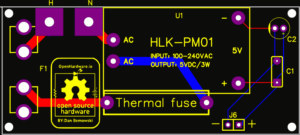 There is nothing fancy with the power supply board. It is based on the standard